Due: Tuesday, February 17, 2004, Midnight
Credit (U-grad): Approximately 6 points (Relative, and very rough absolute weighting)
Credit (Grad): Approximately 5 points (Relative, and very rough absolute weighting)
Note: In assignments I will ask some rhetorical or optional questions. While they are optional, I often use such questions as a source of exam questions. Hence, even if you do not do them, it is a good idea to think how you might go about answering them.
You can do this assignment in either Matlab or C/C++. It may be slightly easier in Matlab, but it may also be a good opportunity to begin (or continue) learning about building vision systems in C/C++ if you expect that this may be in your future. Most of the functionality that one has in Matlab exists in libraries (or should be added to them). Libraries that you may wish to consider include the Intel vision library, Gandalf, and ours (KJB). Naturally I have a preference that our library is used and extended as needed which is largely done by creating wrappers for existing software components. (Those that are familiar with the library should consult the man page for "diagonalize" for this assignment).
For those wanting to use the KJB libray, I have provided an example program showing the use of some functions along the lines of what my be helpful in the assignment in this directory . There are hopefully enough comments in example.c to get you started. The file compile_line deals with the complexities of including and linking. The files matrix.txt and image.tiff can be used as example data for the program.
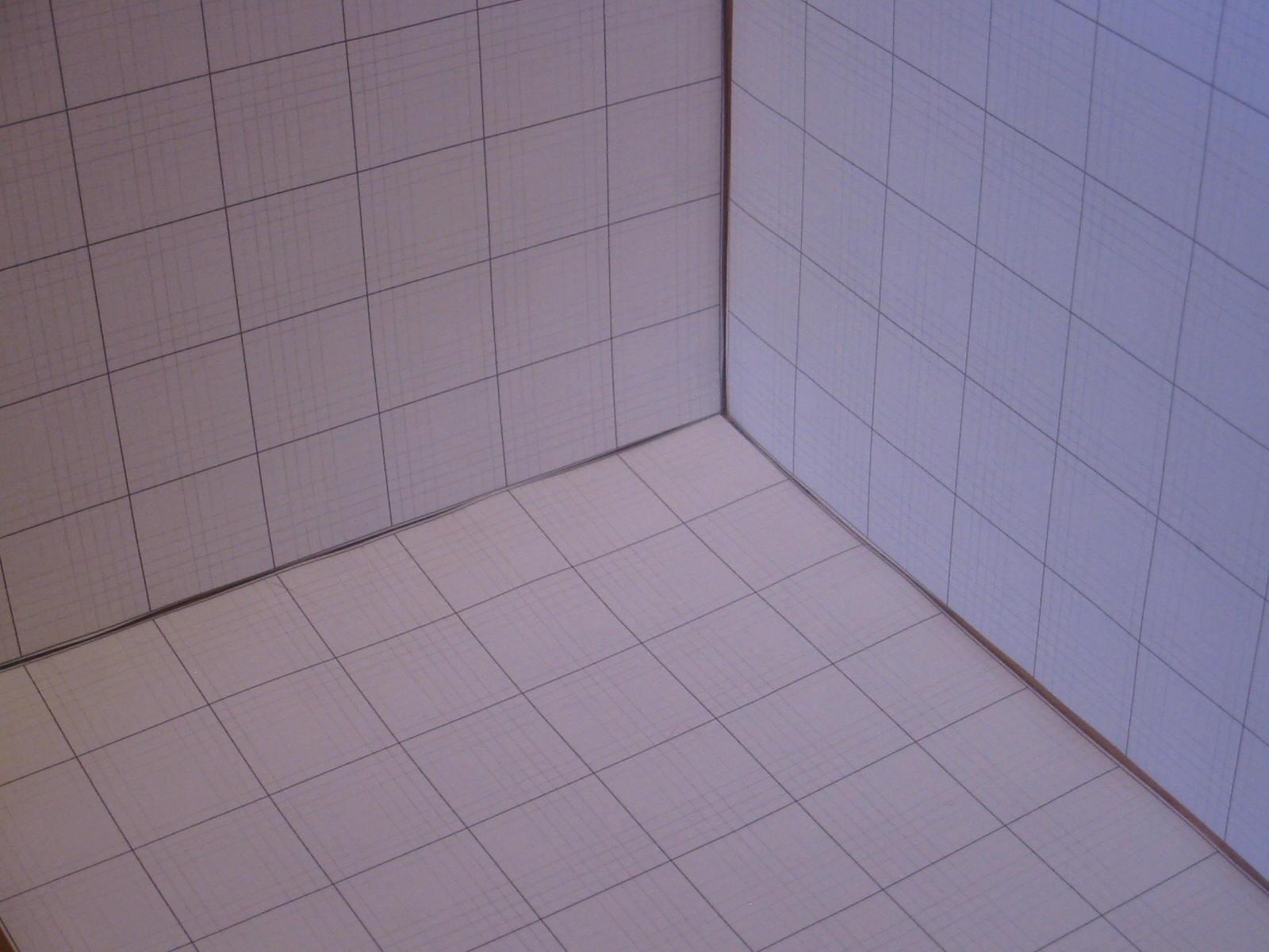
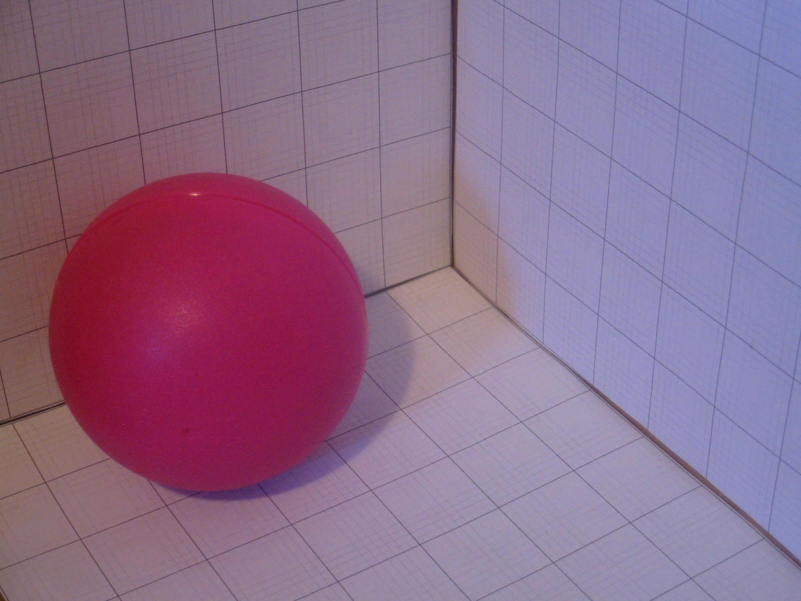
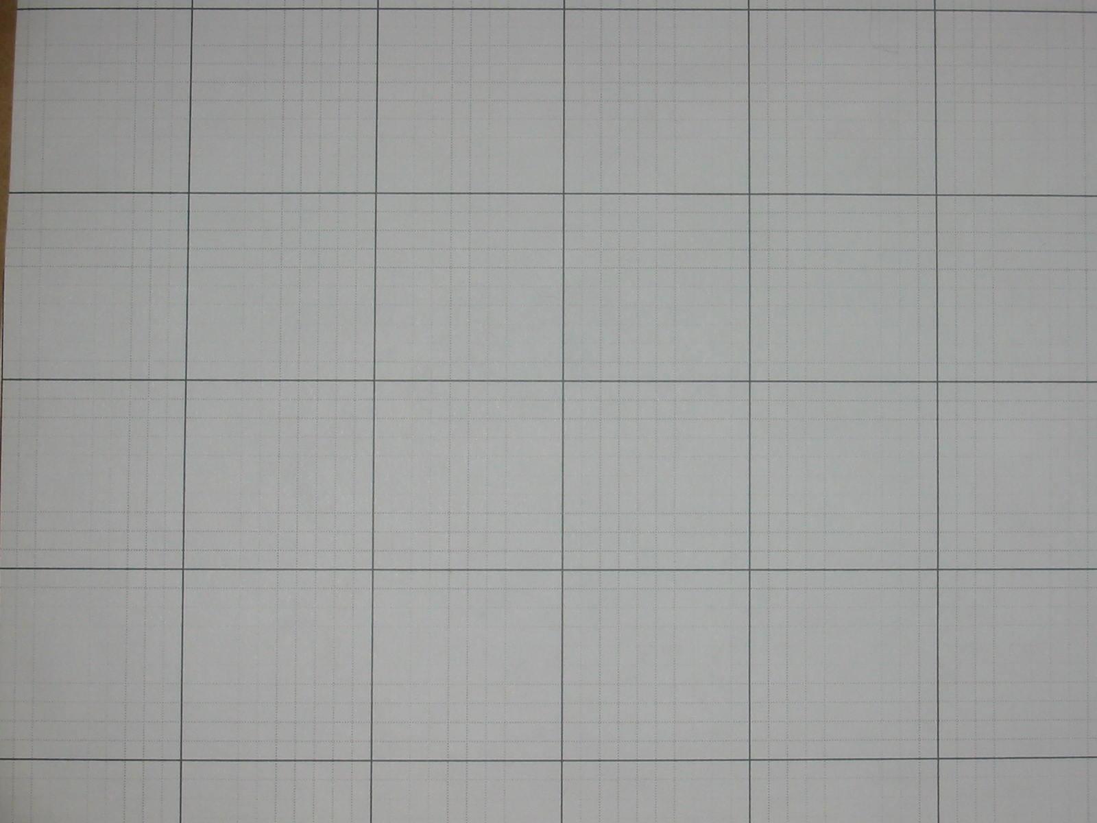
Use at least the first one of these images
|
IMG_0862.jpeg
(tiff version)
|
(tiff versions are supplied in case there are problems with the jpeg versions or the compression artifacts are giving you trouble, but note that the tiff versions are BIG!) |
To get the pixel values of the the points, you need to either write a Matlab script to get the coordinates of clicked points, or you can use the program kjb_display (PATH is ~kobus/bin/linux_386_p4, MANPATH ~kobus/doc/man) which is a hacked version of the standard, ImageMagick verison of "display", or you can use some other software that you may know of. If you use kjb_display, use alt-D to select data mode. Then the coordinates of pixels clicked with the third button are written to standard output.
To set up a world coordinate system, note that the grid lines are 1 inch apart. Also, to be consistent with the light direction given later, the X-axis should be the axis going from the center leftwards, the Y-axis is going from the center rightwards, and the Z-axis is going up. (Note that it is a right handed coordinate system).
Using the points, determine the camera matrix (denoted by M in class) using linear least squares. Report the matrix.
Using M, project the points into the image. This should provide a check on your answer. Provide the TA with an image showing the projected points.
Lets assume that the camera is has perpendicular axes, so that we can assume that the skew angle is 90 degrees. Use the equations on page 46 of the text to ccompute the intrinsic parameters of the camera.
In particular, you will recover the orientation and location of the camera, which will be used in the next part. Report your estimates.
As a further direct check on the results, Scott reports that for this image (tiff version) the camera was 11.5 inches from the wall. This can be used to compute alpha and beta more directly.
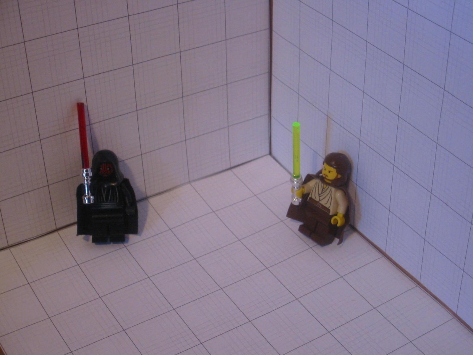
The TA reports that the light was at coordinates 33, 29, and 44. Ask yourself if this makes sense given the shading of the objects in the images that have objects. We now want to render a sphere into one of the images with one or more objects in it with plausible shading. Using the Lambertian reflectance model, render a sphere using any color you like. In order that this assignment does not rely on having taken graphics, we will accept any dumb algorithm for rendering a sphere (and we will provide help to those who want it). For example, you could model a sphere as:
x = x0 + cos(phi)*cos(theta)
y = y0 + cos(phi)*sin(theta)
z = z0 + sin(phi)*R
Now step phi from -pi/2 to pi/2 and step theta from 0 to 2*pi (If your sphere has holes, use a smaller step size).
For each (x,y,z), the normal direction for the point on the sphere can be determined (you should figure out what it is). From this, you can decide if this point is visible, and refrain from displaying it otherwise. To decide if a point is visible, consider the tangent plane to the sphere at the point, and compute whether the camera is on the side of the plane that is outside the sphere. If the camera is on the inside side, then it is trying to view the point from the inside (or backside), and since a sphere is a solid object, there must be something which obscures the view. This is called backface culling. See if you can figure out how to compute which side of the plane the camera is on without this hint.
Note that you are not being asked to employ graphics software such as OpenGL. Just color the particular pixels in a copy of the image appropriately to create a sphere.
You should specify the sphere location and diameter that you have chosen to render.
This part is optional!
A) Add a specularity on sphere. B) Render the shadow of the sphere.
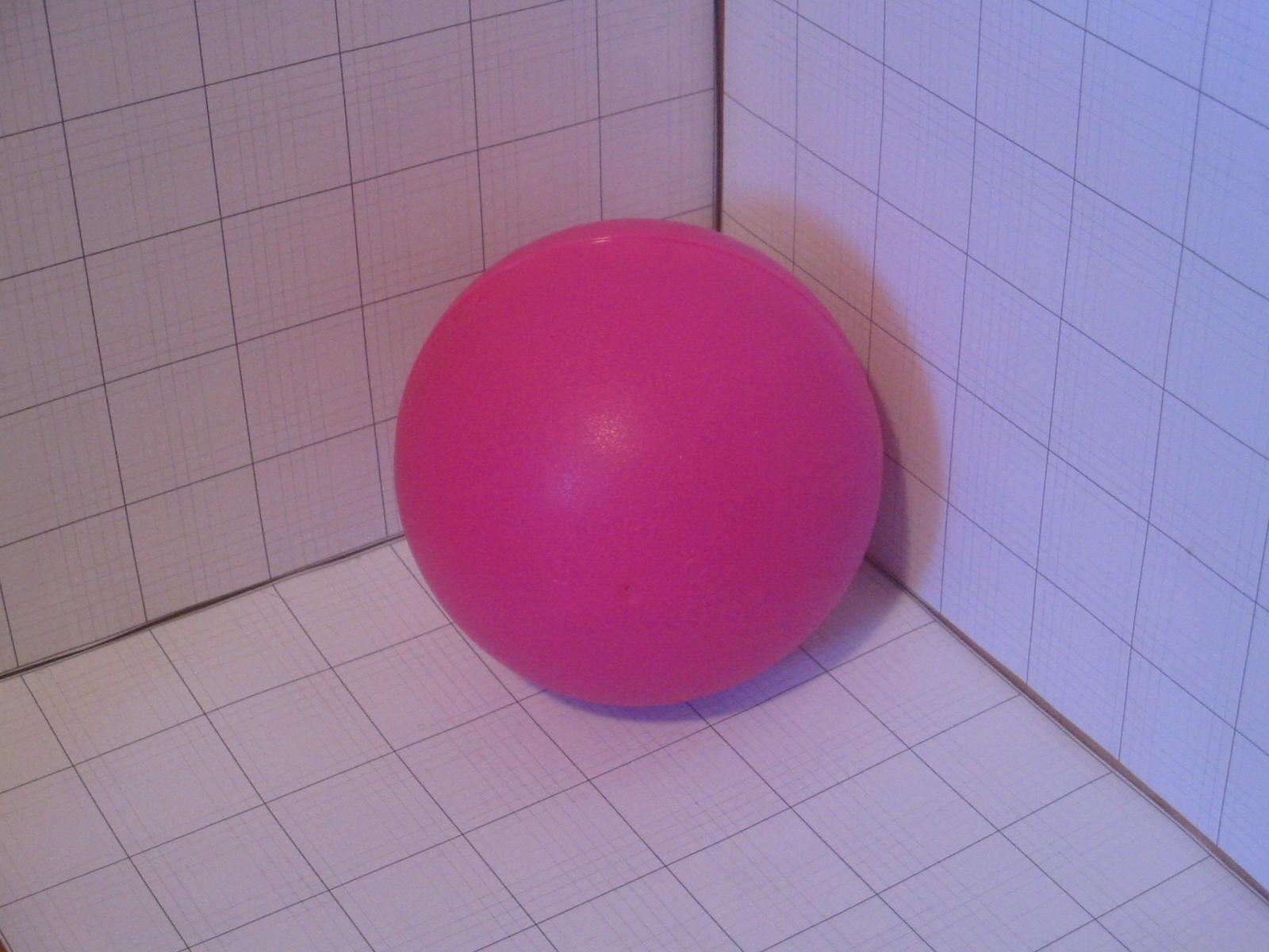
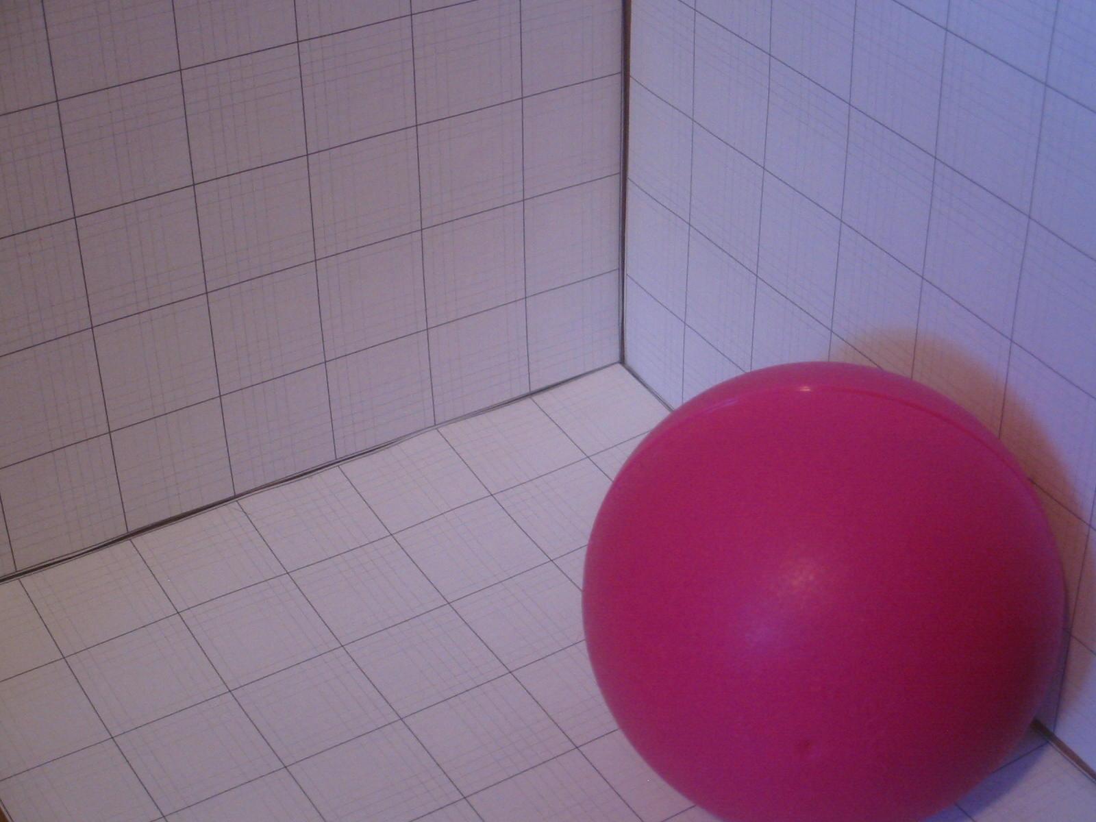
Can you explain the colors and the shadows in the images (say this one?)
To hand in the above, use the turnin program available on lectura (turnin key is cs477_hw2).